
|
Christophs Tape pages - MX 55 - Network remote control - |
|
Digital or Analog? - The best of both worlds
|
|
I always receive many recorded tapes whose recordings I consider worth keeping, e.g., with music I don't know yet.
Sometimes other people who still have tapes but no tape recorder anymore get in touch with me.
Noisy microphone recordings of a family celebration from 40 years ago are sure to hold some nostalgic value for the protagonist (or his heirs).
I then digitize such recordings using one of my tape recorders, whereby the choice of device depends on the track position, speed, etc. of the tape. The MX-55 is often used for this purpose. Unfortunately, my MX-55 and the PC I mainly use are several meters apart. It's a bit annoying to constantly have to switch between the PC and the MX-55 to rewind the tape a bit and restart the recording on the PC. I built a cable remote control for the MX-55 some time ago, but it could be a little more convenient. That's why I came up with the idea of controlling the MX-55 remotely via my PC (since I'm already sitting in front of it). After some soldering and programming work, here is the result. This is already version “1.3,” but certainly not the last, as you can see below in the “ToDo” section. Originally, an “AVR-NET-IO” circuit board was intended to serve as the interface between the tape recorder and the network. However, the limits of this “black box” were quickly reached. However, the limits of this “black box” were quickly reached. That's why I've now switched to the much more flexible Arduino. |
|
|||
|
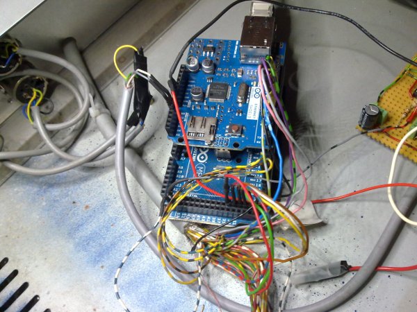
The hardware
Not yet installed, only connected. |
|||
 |
|||
| The heart of the design.
An Arduino Mega 2560 with an Ethernet shield attached, featuring an ATmega2560 processor. This board also has a USB port, 54 digital inputs/outputs, and 16 ADC inputs (10-bit analog-to-digital converters). The interesting thing about this design (with Ethernet shield) is that all commands sent and all data received are routed via a single standard network cable. This means that the MX-55 can be integrated into any standard home network. Theoretically, a Wi-Fi solution would also be possible, but since I have a network connection everywhere anyway, the additional effort was dispensed with. |
|||
|
|||
 |
 |
||
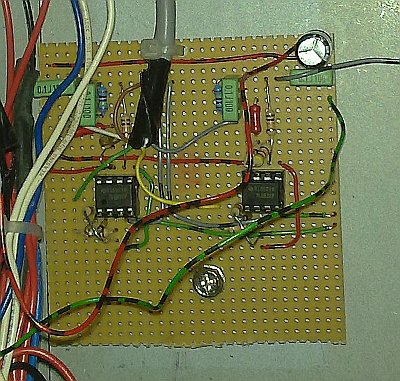
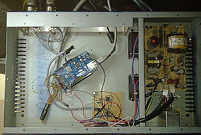
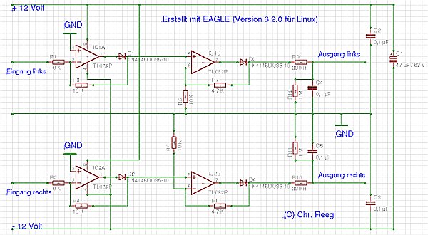
| The circuit board for the output level indicator is built with two dual operational amplifiers. This is a test version; a professional circuit board is still being manufactured. | Everything together in the housing. In case anyone is wondering why I am using such a large housing for so little electronics—I just happened to have it lying around. In addition, a switching power supply (visible on the right) was already installed, which provides me with all the voltages I need (+5 volts, +12 volts, and -12 volts). | ||
|
|||
 |
|||
| The circuit diagram for the level meter. | |||
|
|||
|
The front end (written in JAVA)
|
|||
 |
|||
|
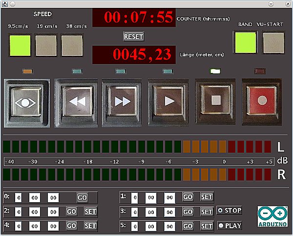
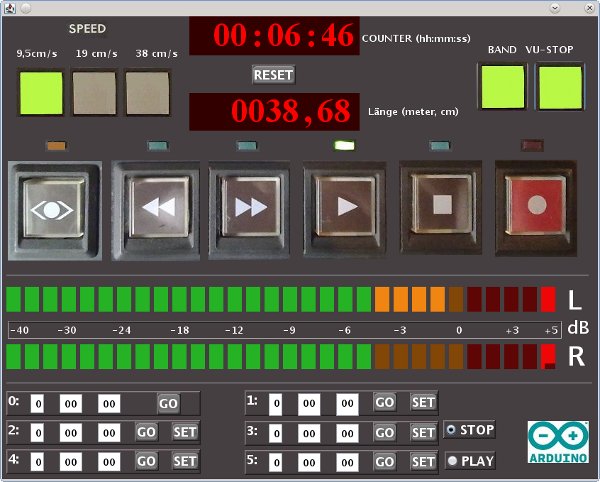
The program view, followed by a description of the operating and display elements:
The speed indicator is located at the top left. The currently set speed is displayed here (in light green). Unfortunately, the remote control interface does not have the option to switch speeds. Only signals for evaluation (speed A tally, speed B tally) are available. These are fed in via two of the Arduino's digital inputs and evaluated by the software. Counter The running time of the tape is displayed here in hours, minutes, and seconds. Länge Used to display the “used” tape length in meters or centimeters. Reset Resets both displays to zero. These displays use one of the Arduino's interrupts. This monitors and evaluates the speedometer signal of the MX-55. The control buttons (rewind, fast forward, play, stop, record). There is an LED above each key that indicates the operating status. Recording is started by clicking on the record button. It seemed a little difficult to me to implement the function as in the original (pressing the record and play buttons simultaneously). These buttons are software-controlled and each switch one of the Arduino's switching outputs. The “CUE button” on the far left occupies a special position. This allows you to enable a co-operation option for fast rewinding. The volume is reduced by -14 dB. The “Band” indicator shows whether a tape is inserted. This is controlled by the left tape guide lever. The VU meter. Since this board has several ADC inputs, as mentioned above, they should also be used for something. The rectified output signals of the MX-55 are fed into two of these inputs and used to display the signal via LED bars. The displays were calibrated using a level meter from audio studio technology and are reasonably accurate. The response time was set to approx. 500 ms. In order to obtain a reasonably fast display of the VU meter, the input values must be queried quite frequently (every 35 milliseconds). This causes quite high CPU usage. Therefore, the display must be explicitly switched on (VU Start) and can also be switched off again (VU Stop) independently of the rest of the program if the computing power is needed for something else at that moment. As can be seen in the picture, a peak indicator has also been implemented. The highest value remains on the display for approx. 0.5 seconds and is then deleted again. The Counters Below you can see 6 counters (labeled from 0 to 5). Counter number 0 resets the tape (when you click on “GO,” the (software) counter is reset to zero). Counters 1 to 5 take over the current status of the (software) counter when you click on “SET”. After that, you can navigate to this location by clicking on “GO.” This means that 5 different band positions can be stored. With the selection on the right (Stop/Play), you can choose whether the tape should be started (playback) or stopped when the tape position is reached. |
|||
|
|||
|
To Do
|
|||
| • Build an improved, frequency-linear rectifier circuit. --> done • Build a frequency counter for real-time display of the tape length. This would also make it possible to implement an autolocator function, which could be used to move to any adjustable position on the tape. This is proving more difficult than initially expected. The problem is the extremely short pulses (approx. 10 microseconds) sent by the MX55. These times are more than 100 times lower than the ping times in my network (> 1 millisecond). Therefore, the counting and evaluation of the pulses must be performed directly by the microprocessor. I am currently experimenting with programming an Arduino board to solve this problem. --> done • Code optimization to reduce CPU usage. • Variable speed control. |
|||
|
|||