
|
Christoph's Tape Pages - FAQ - FAQ DIN/Cinch- |
|
Question:
I have an older tape recorder. The inputs and outputs are 5-pin DIN sockets. The inputs and outputs on my new system are all Cinch sockets. Now I've bought a Cinch to DIN adapter cable, but it doesn't work properly. The playback from the tape recorder sounds quite good, but everything is distorted during recording. Answer: Answer: It is not enough to simply make the shape of the plugs “compatible.” There is another significant difference between the two connection types. This difference is the height of the voltages used. The signals used for recording at Cinch average approximately 100 to 150 mV (millivolts). The voltages used in DIN are between 1 and 5 mV. This shows that any device with Cinch output sockets will hopelessly overload a device with DIN input sockets during recording. The obvious idea of closing the level control on the tape recorder to such an extent that the needles of the level meters move within the “normal” range unfortunately does not work either. The reason for this can be found in the design of the input stages (and their arrangement). Basically, an initial amplifier stage follows directly after the input jack. This is mainly intended to decouple the input of the tape recorder from the output of the amplifier (radio, etc.). Only after this initial stage (and any further stages) does the output control take place. If this output control were to be implemented directly behind the input jack, this would result in varying loads on the amplifier's output stage (radio, etc., depending on the control setting), with negative side effects. From the above, it is clear that even this first amplifier stage was overloaded by the excessively high input signal. The signal transmitted to the output level controls is therefore already significantly distorted. The solution to this problem lies in inserting series resistors in the recording branch. The most universal solution here has proven to be the direct installation of the resistors in the 5-pin DIN connector. The resistance value is not critical, as the modulation can be readjusted over a wide range using the modulation controls. In practice, 470 kOhm has proven to be a useful value. Metal film resistors should be used wherever possible, as these have lower noise and a smaller tolerance than carbon film resistors. |
||
 |
||
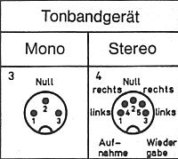
| As a little help, the pin assignments for the diode (DIN) connectors are shown above (viewed from the solder connections). | ||
| ↑ back to top ↑ | ||
|